| ||||
  | ||||
| The cockpit The installed instruments are: air speed indicator, altimeter, a mechanical rate of climb indicator, a Ball electric vario, tachometer, EGT gauge, fuel quantity gauge, battery voltage gauge, bank indicator, magnetic compass plus 720 ch Dittel radio with head set. The bright white spot on the left side of the instrument console is a mirror to see the prop position for retraction into the fuselage. I also have a Garmin 90 GPS fitted to the canopy frame with a cable to the plane battery. The cockpit is crowded for the pilot. There are two cranks, one for the flaps on the left side and another for the engine retraction on the right side. I am a bit worried about of how to bail out in an emergency. Other possible hazards include a lead acid battery in the nose (in front of rudder pedals) and the fuel tank as the pilot back rest. Well, similar arrangement can be seen in many ultralight airplanes and it also was adapted for the type certificated serial production model PIK-20E. However, in the latter, the tank is of crash resistant kevlar fiber whereas in my JT-6 it is of brittle fiberglass. | ||||
| ||||
JT-6 engine installation. The first engine tested, the 33 hp Canadian Kohler, determined the engine compartment size for the JT-6. This created a problem when fitting the larger 45 hp Rotax 502. The engine compartment opening is only 28 cm wide, allowing no space to fit normal cylinder cooling air baffles. I solved the problem with a unique arrangement of a folding plate (0.5 mm 2024 aluminium sheet) with two piano hinges. When the engine is retracted, the cooling plate is pressed agaist the cylinder fins (red arrow in the picture below). Heavy tape was added to the aluminium sheet to prevent vibration and cracking. Several exhaust mufflers were tested with the Kohler and Rotax engines until the final one was well tuned for good power with low weight. I also carved several propellers of laminated birch. The finishing is of fiberglass/epoxy covering with epoxy paint. | ||||
 | ||||
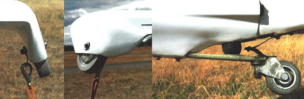 | ||||
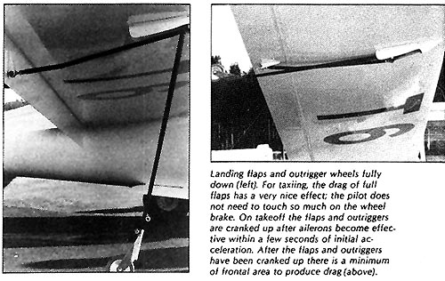
| Landing gear additions. Originally I designed wing mounted retractable outrigger wheels for the JT-6. They were operated together with the flaps and were basically OK except that the flap mechanism inside the wing did not tolerate the high loads generated if the outrigger wheels hit an obstacle on landing. After about five years of flying I replaced the outrigger wheels with wing tip wheels adding tie down brackets as well. The tail wheel is steerable with a steel spring arrangement between rudder and the tail wheel fork. | ||||
| Back to JT-6 page | ||||
|
|
