|
[[Home | Experimental Aircraft | JT-5 Autogyro |3D Modeling] |
||||||||||
|
||||||||||
| These
pages have been created to help builders in various countries to
complete their JT-5 autogyro project. I shall add new pictures and text
every now and then to explain details and answer builder questions. So,
the pages are a kind of a FAQ pages.
|
||||||||||
| General layup information:
For those who have never used epoxies I have included SP Ampreg 20(TM) data sheet, which gives very valuable information to use any epoxy. Glass/epoxy layup and vacuumbagging involves a myriad of tricks and tips. Most of them, I belive, are explained in good books available from EAA and similar sources. And there sure are many new methods I dont even know. One essential know how is how to roughen the previous glass layup surfaces before continuing to the next layup or bonding step. This a very important step since the bond between the two layers will be very poor unless the roughening is properly made. Two methods are in general use: 1) You can roughen the surfaces by sanding them. Sanding will remove the glossy epoxy surface and lift tiny glass filament tips up from the surface. However, too much sanding will weaken the fabric by cutting too many threads. This was the method I used in making my JT-5 autogyro fuselage pod, fuel tank, tail surfaces and blades. 2) A new method developed by the glass sailplane industry on the seventies is to layup peel ply, nylon fabric on the free surfaces later to be bonded to another surface. You peel off the nylon fabric after curing. This is a fast and easy method and does not harm the glass fabric below. You can also combine these two methods. Glass content in hand layup: The strenght of the final glass layup laminate depends on
filament orientation and what is the glass content of the layup. It may
vary videly, say 30....60 percent when unidirectional rowing is used.
The glass percentage and filament orientation are especially important
on highly loaded unidirectional laminates such as rotor blade spar and
landing gear legs. However, reaching high glass content by hand layup is
difficult. You may try to copy techniques used by the industry, like
pulling the unidirectional rowing through a liquid expoxy bath and then
through a tight nozzle which removes excess epoxy. Anyway, to reach a
glass content of 50 percent should be the goal.
|
||||||||||
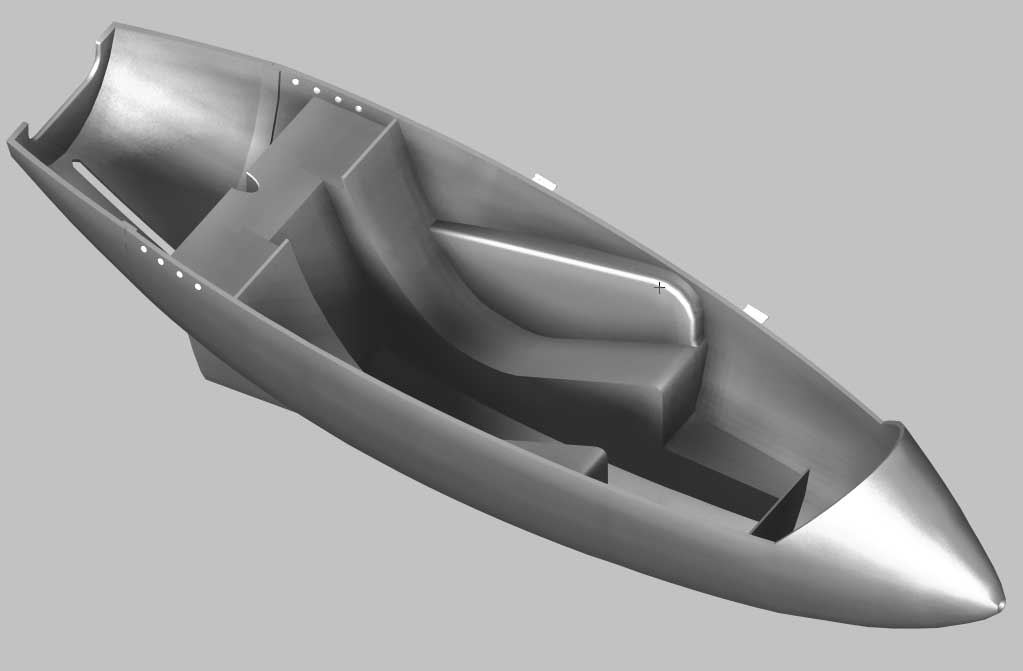
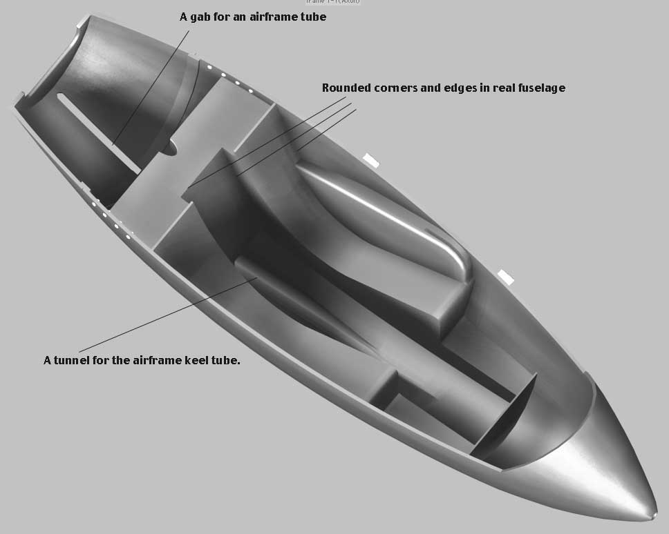
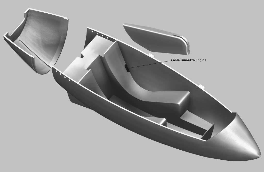
| More pictures on the fuselage pod construction: Notice, that aft part of the pod is a separate non load carrying structure attached by screws (not shown) to the main pod part. Although the aft part is shown here as 10 mm thick (due to modeling simplicity) it should be made as a 1 mm thick glass/epoxy laminate. Most of the seat and tank corners and edges were rounded in a real fuselage although shown here as sharp edges. All the fuel tank side walls were laminated first (both inside and outside for perfect sealing), intake tubing was added as well a drain walve and finally tank cover was laminated on on top of the tank using a aluminium sheet as a template (outside, of course. It was removed after curing). Notice the two tunnels going through the tank, one for the airframe keel tube and one for the throttle and prerotation cables.
Notice that I have created new Pod and Canopy sections!
|
||||||||||
|
Questions and Answers: Q: How do the landing gear secure into the tubes? Q: Would you be able to send me weight and balance info, please??? Q: What is the gyro performance at higher elevations and temperatures? Q: In vacuum bagging the cockpit, is this the correct sequence? I've done a lot of glass work over the years, mostly with cars and boats and lately a camper roof, but this will be my first entry to the vacuum bagging world. Generate Male Plug, A: Generally correct except one point, you should vacuumbag the outer skin and honeycomb together to get a good bond. A special type of honeycomb is needed which will bend and adapt to double curvature surfaces. You should prebend the honeycomb to the pod shape. I did not vacuumbag the inner skin but it may a better choice to do. If the corematerial is plastic foam instead of honeycomb the inner skin does not need vacuumbagging. Q: How do you feel about bronze welding (Sifbronze) instead of regular welding for the airframe?
|
||||||||||
| Technical Photo Gallery:
|
||||||||||
| JT-5 3D model. To view some construction details, I have modeled the JT-5 autogyro using formZ RenderZone modeling
software. The model even includes the Limbach engine and a pilot (me!)
and shows details down to the nut and bolt level. Make a visit to my 3D page.
|
||||||||||
|
[[Home | Experimental Aircraft | JT-5 Autogyro |3D Modeling] |
||||||||||